Tyman Sin
ts835@cornell.edu
Tyman (CS MEng '20) took lead developing the overall software architecture and testing the cohesive system with his car in Arizona. Both partners contributed to the report content.
For this project, we created a head unit for vehicles that can display information that is not available on the standard gauges, can display and record dashcam footage, and can display a primitive navigation system. Automotive diagnostics are very important for keeping cars running properly. All cars sold in the USA after 1996 have an OBDII (On-Board Diagnostics II) port which can be used to access information about the vehicle, including live data and check-engine codes. With most older cars lacking key information or functionality we decided to provide our own system.
For this project, we used a Raspberry Pi as the main computing platform. This was connected via bluetooth to a OBDII adapter that plugged into the car port. A large touchscreen display was connected to the Pi to display the relevant graphics and information. A touch-functional menu was implemented allowing navigation between engine status, dashcam, and GPS tabs. A camera module was connected to the Pi to display realtime dash footage and offer the driver an option to record and save the dash video should they wish to. A GPS unit was connected to the Pi in order to track the location of the car while driving, this information was used to plot the realtime location on a map displayed on the screen. The GPS also supplied the date and time which was displayed at all times on the screen. The entire system was powered by the car's 12V cigarette adapter port.
A modular approach
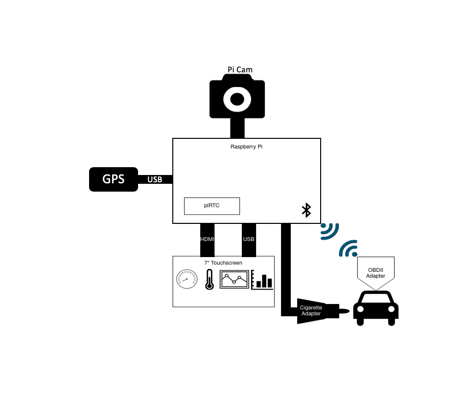
The system was designed to include an OBDII module, a camera module, a GPS module, and a touchscreen module all connected to the central Raspberry Pi. The entire system was to be powered by the car through a 12V adapter. All modules would be connected through physical ports or wires except the OBDII scanner, that would be connected over bluetooth to the Pi.


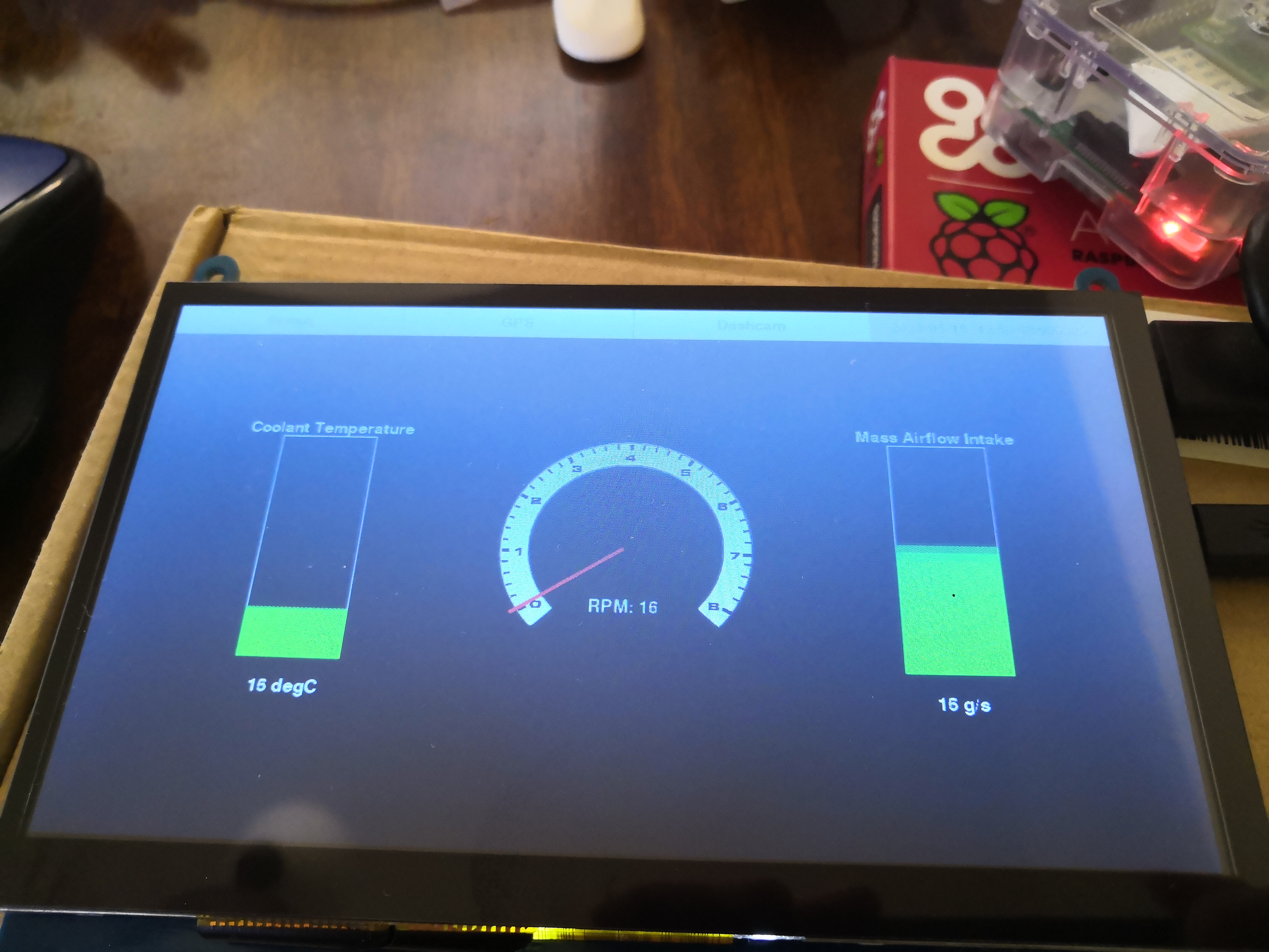
We designed the system interface such that it would have a top bar menu with touch sensitive buttons to switch between functions and "screens". The default screen upon power on would be the vehicle status screen. We envisioned displaying information such as revolutions per minute (RPM), engine coolant temperature, and mass airflow at the engine intake (MAF). We pictured dynamic bar charts for the coolant temperature and the MAF while using a circular dial with a dynamic needle for the RPM gauge. The bar charts would linearly adjust their color from green to red as they increased in value.
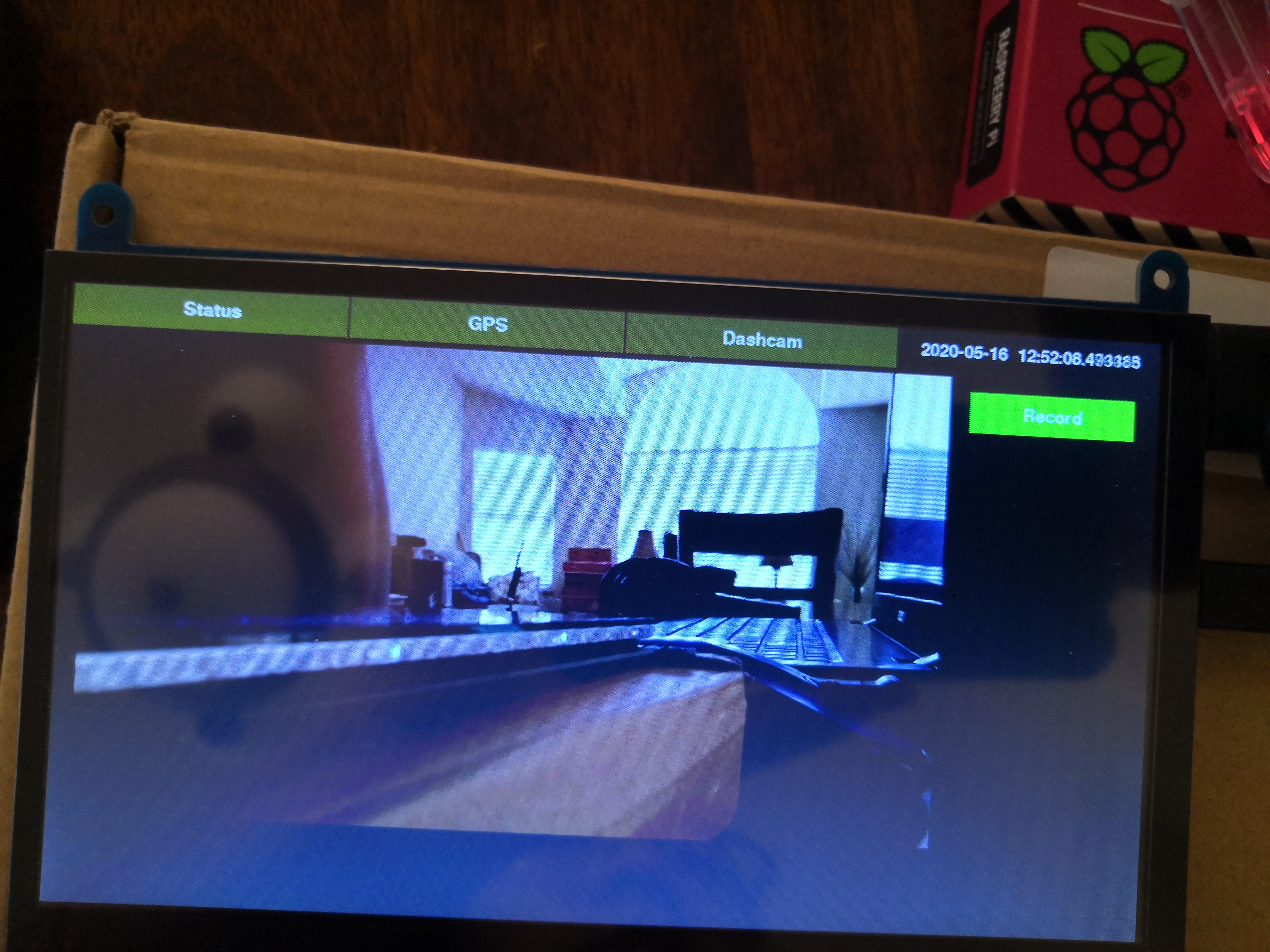
The dashcam screen was designed to display a live feed from the camera to the screen when active. It would feature a record button that could be pressed to enable a live video recording that would be saved to the system when the user pressed the stop button. A red dot would appear while recording to make clear to the user that it was actively recording.
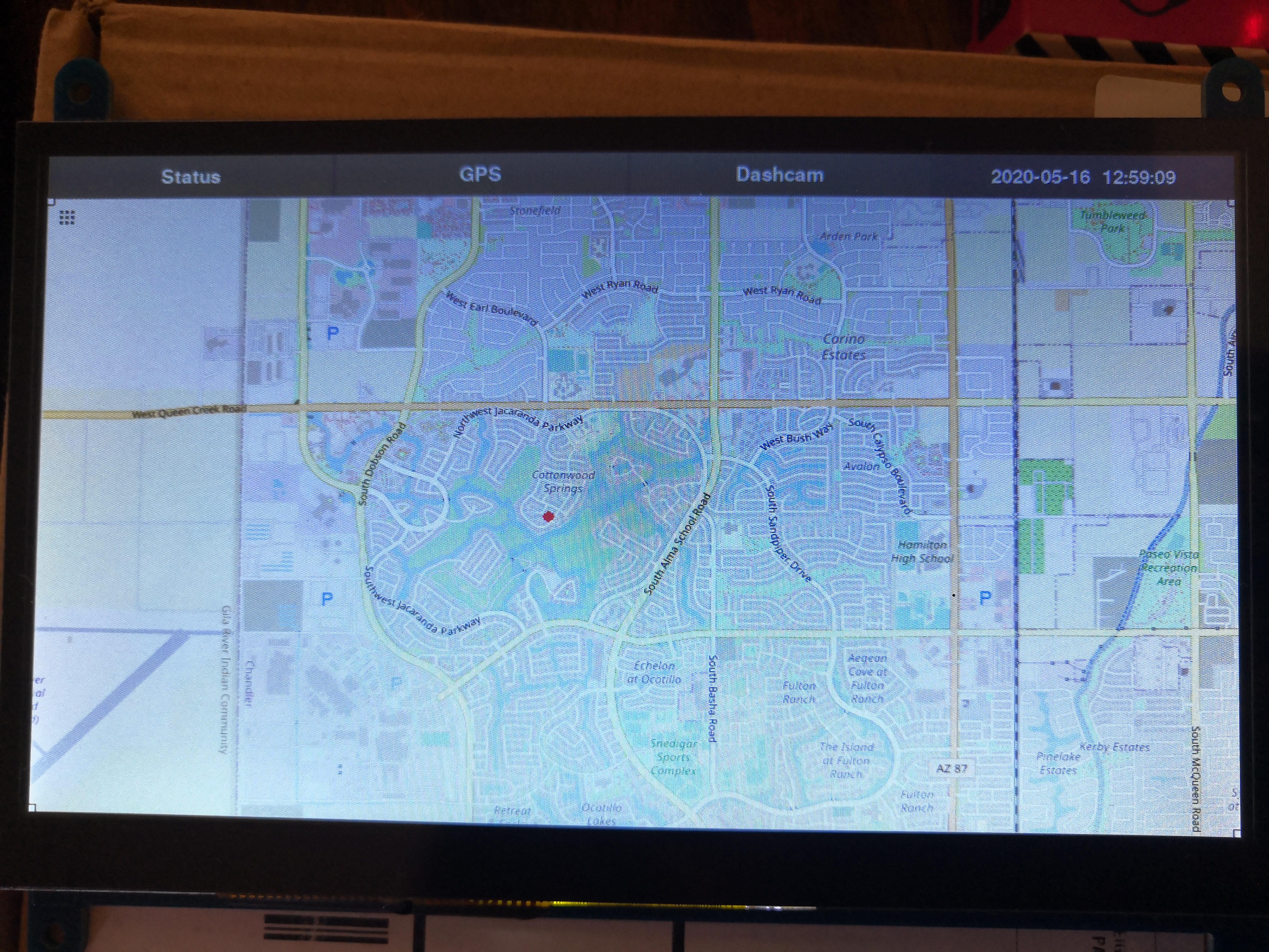
The GPS screen was designed to overlay a green indicator corresponding to the car location on a background map tile. In theory, the map tile would adjust as the indicator neared the boundaries and render more map and shift to keep the car location within the bounds of the tile. The project initially intended to make use of Open Street Maps to pull map data and render the necessary map tiles for the region surrounding the location at the time of display.
We built this system in modules over the duration of the project. Each week we worked on a different subsystem before merging it to the master system at the end of that week of development. This enabled better time management and also version control incase one of the modules proved faulty upon integration.
OBDII BLE Scanner: The first module we worked on was the OBDII scanner itself. The install of the necessary software was relatively straightforward with no issues. The bluetooth connection was more difficlut to set up, but both the OBD install and BLE connection setup can be found in the github repository here.
Graphical User Interface: The second module we worked on was the touchscreen and default status screen. With knowledge of pygame from the labs, we decided to stick with it to implement our graphics and touch interactivity. Pygame is a set of Python modules for video game development. It is free to download and runs on most platforms and operating systems. Pygame comes preinstalled on Raspbian, however if needed, the install info can be found here. Ryan ran into issues getting started with the Raspberry Pi because he did not have a keyboard or monitor, only his laptop. After borrowing a roommates keyboard and configuring connection to wifi according to this guide, the connection to the pi over the home wifi proved incredibly slow when using ssh. Given this, a VNC was setup using the program VNC Viewer and then connecting the pi to the home network directly via an ethernet cable. This Raspberry Pi configuration page as well as this youtube guide proved helpful in establishing the setup. In setting up the screen module itself, it required a few added lines to config.txt which is outline by the product page here. While this worked for the display functionality, we ran into issues with the touchscreen. In an attempt to use fbcon, as we had in lab during the semester, the screen registered touch but the data did not correspond to the correct location on the screen. Eventually, we found a solution by starting X11 for a single application as this guide details. By adding
startx --kiosk --
to .bashrc, the touchscreen properly worked. Another issue we faced was specific to the RPM gauge. When using pygame to rotate the needle we ran into two problems. The first was if you do not specifically set the alpha values of a surface, in our case the rect for the needle, when rotating any amount that is not a multiple of 90, pygame adds a padding to the rect which essentially makes it a large square of color instead of a thin needle. We fixed that by using pygame.SRCALPHA in creating the needle surface.
self.__needle = pygame.Surface((radius // 32, radius), pygame.SRCALPHA)
The second issue occured when rotating more than 0-90 degrees. When doing so, the rect would no longer be centered on the gauge. We fixed this by recognizing that the rect’s previous left and top was no longer the new left and top so we had to adjust the needle postion by either the width, height, or both of the rect depending on what desired rotation was and what quadrant it fell into. For example, if the rotation angle fell in the third quadrant (180 - 270) where 0 is directly pointing down from the center of the rpm gauge, the left was set to center of the rpm gauge less the width of the needle rect, and the top was set to center of the rpm gauge less the height of the needle rectangle. Note, we used a png file for the RPM gauge background which can be found here.
elif self.__needle_angle < 180 and self.__needle_angle ≥ 270:
	screen.blit(rot_needle, (x - rot_needle.get_width(), y - rot_needle.get_height()))
And the end of testing, the default status display upon power on looked as shown below:
Dashcam: The third module we worked on was the dashcam. We decided to use the piCamera library with the project since it comes preinstalled with Raspbian. We created a live feed by using a preview that essentially hijacked the framebuffer to overlay the camera feed on our pygame GUI. When the dashcam menu button was pressed the preview window was shown and when the user navigated away from the dashcam menu button it was hidden. While viewing the dashcam feed, the user could elect to press a record button that was enabled through pygame. When pressed, it would begin saving a video file in one minute increments, within a folder that was labeled with the time stamp at the press of record. The reason one minute increments were used was to enable error checking. The pi is only capable of checking if there was a successful recording when the recording is saved to file, and so by recording in one minute increments, the system is able to check every minute if there was an error or not. The picamera library has a macro that enables cutting of video which made this an easy implementation. When the user desires to stop the recording, they press the stop button enabled through pygame and the latest one minute recording is stopped and saved. The user may then access the video files by removing the miniSD card from the pi and placing in a computer. One bug we encountered with the record functionality was that when a user had pressed record then subsequently navigated to another tab and then returned to the dashcam tab, the record button would reappear despite the device actively recording. We tracked this bug to a line of code that reset a recording flag whenever the user navigated to the dashcam page. By removing the line prompting the flag change the bug was resolved. The finished dashcam page looked as shown below:
GPS: The GPS module was the last piece of the project to arrive due to COVID-19 related logistic delays. To use the GPS unit, we installed gpsd a daemon specially designed for gps and commonly used on Unix-like software, its documentation can be found here. To install we simply ran:
sudo apt-get install gpsd
To then use the daemon we installed a corresponding python library through:
pip install gpsd --user
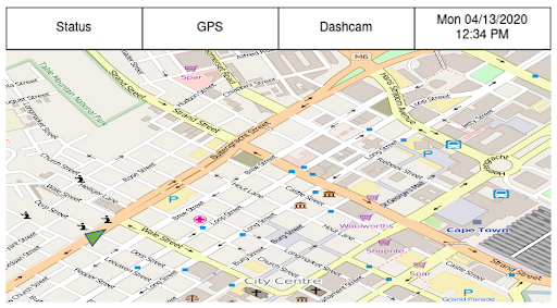
The user option was added so that the install would be constrained to the active user and not the enitre system. We then worked on implementing a dummy test system so that when the GPS module arrived we would be able to take the data sent from the GPS and plug it into the already built module. The project had orginally hoped to use Open Street Maps to pull and render our own slippy map, but after diving deeper into the steps that would be required to bring this to life we realized that it was out of scope for our remaining time line. We instead chose to pull a screenshot of an Arizona neighborhood that was large enough to demonstrate the feasibility of our system. To do so we navigated to the export tab of the open street map site here. We then were able to specify the bounds that we wanted for the tile and then download the specified region as an image. We used pygame to display this map "tile" and then used a small dot to represent the cars location. By mapping a linear function between the number of pixels on the screen and the longitude and latitude bounds of the tile, we were able to take an input of longitude and latitude from the GPS and convert it to pixel values to change the location of the dot representing the car's location. The system was implemented in such a way that theoretically, if we had taken a series of map images or "tiles" and linked their respective longitude and latitude bounds, that when the system approached the bounds of a tile, the system could have changed the background tile and the function relating pixels to the new bounds. This would still not be a final solution however. To implement a navigation system that appeared as if the map was scrolling and not incrementally shifting, it would have required more time and back end then our remaining timeline allowed. Our final GPS screen appeared as show below:
We largely met the goals outline in our original project description. The only obvious difference from our project vision and the final system was the navigation system. As we spoke to above in the GPS section of Build + Testing, we chose to change the scope of our navigation system based on time constraints. Despite being open source and free to access, we underestimated the necessary back end that would enable a scrolling map feature with large bounds. Had the project had two more weeks we believe we could have given this more complex navigation system a shot. For the purposes of this project though, our final system still demonstrates the vision and provides a first step in the eventual implementation of a home navigation system. All other aspects of the system were completed to original specification. Our system is capable of displaying real time engine data in a visual format, it is also capable of displaying a live dashcamera feed with record functionality.
As mentioned above in Results, if we continued to pursue this project we would have worked to implement a more functional navigation system with a scrolling map.
We may have also explored a menu funtionality that could enable the user to dynamically choose which gauges or engine information to display on the status screen.
As for the camera, we had spoke about perhaps a backup camera functionality, but realized that with the project's budget we would not be able to afford it given it would take a Raspberry Pi Zero and a second camera module; however, it could be a fun future pursuit for the system.
ts835@cornell.edu
Tyman (CS MEng '20) took lead developing the overall software architecture and testing the cohesive system with his car in Arizona. Both partners contributed to the report content.

rpb228@cornell.edu
Ryan (MechE MEng '20) supported the software development virtually from Ithaca and took lead on writing the html. Both partners contributed to the report content.
Take your own shot at building a pi cardash!